The Standard Language of Motor Control: CiA402 Profile
What address should you write to and what value should you use to control a motor driver? If each manufacturer uses a different protocol, you would need to write separate control code for every driver. The CiA402 profile is the industry standard that solves this problem. If a motor supports CiA402, it can be operated using the same control sequence regardless of manufacturer.
This article explains the core concepts of CiA402: the State Machine, Controlword/Statusword bit structures, and Modes of Operation with practical code examples.
What is CiA402?
It is a standard profile for motor drives and motion control defined by the CiA (CAN in Automation) association. It is widely used in EtherCAT and CANopen communications.
What CiA402 defines:
- Command values and addresses for turning motors ON/OFF
- Status values and addresses for reading current state
- Operation modes for position/velocity/torque control
Key Object Dictionary Addresses
CiA402 uses the Object Dictionary (OD) address system:
| Address | Name | Purpose |
|---|---|---|
| 0x6040 | Controlword | Send motor state control commands |
| 0x6041 | Statusword | Read current motor state |
| 0x605A | Quick Stop Option Code | Configure quick stop behavior |
| 0x605E | Fault Reaction Option Code | Configure fault reaction behavior |
| 0x6060 | Mode of Operation | Set operation mode |
| 0x6061 | Mode of Operation Display | Current active operation mode |
State Machine
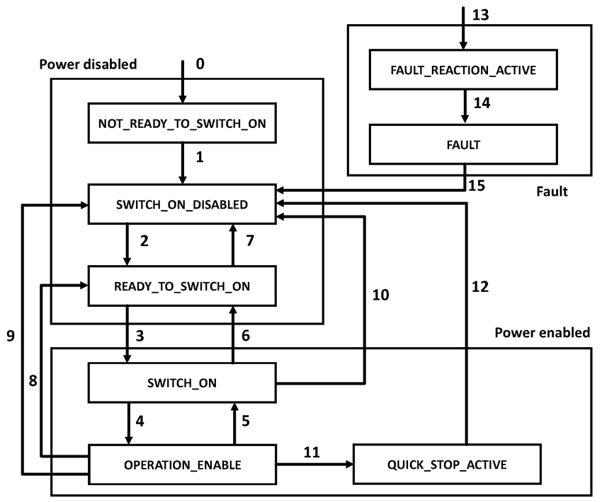
The core of CiA402 is a state machine consisting of 8 states. To turn on a motor, you must transition through states in a predetermined sequence.
State Machine Diagram

CiA402 state machine diagram - divided into Power disabled, Power enabled, and Fault regions
Main Operating States (5 states)
| State | Description |
|---|---|
| Not Ready to Switch On | Initialization phase after power-on |
| Switch On Disabled | Initialization complete, operation not possible |
| Ready to Switch On | Ready for operation |
| Switched On | Amplifier power applied |
| Operation Enabled | Actual operating state - brake released, current flowing, torque generated |
Error Handling States (3 states)
| State | Description |
|---|---|
| Quick Stop Active | User-requested software quick stop |
| Fault Reaction Active | Safety measures in progress after internal alarm |
| Fault | Final error state after safety measures completed |
Controlword and Statusword
Controlword (0x6040) - 16-bit Command Word
This is the register for sending commands to the motor:
| Bit | Name | Description |
|---|---|---|
| 7 | Fault Reset | Attempt to clear error on rising edge (0 to 1) |
| 3 | Enable Operation | Actual ON/OFF switch |
| 2 | Quick Stop | 1 = operation allowed, 0 = quick stop |
| 1 | Enable Voltage | Allow power stage voltage |
| 0 | Switch On | Prepare for power-on |
Statusword (0x6041) - 16-bit Status Word
This is the register for reading the current motor state:
| Bit | Name | Description |
|---|---|---|
| 6 | Switch On Disabled | Initialization or operation blocked state |
| 5 | Quick Stop | 0 = quick stop in progress |
| 4 | Voltage Enabled | Main power normal voltage |
| 3 | Fault | 1 = error occurred |
| 2 | Operation Enabled | Currently operating |
| 1 | Switched On | Power applied state |
| 0 | Ready to Switch On | Ready for operation |
Determining State from Statusword Bit Patterns
| State | Bit6 | Bit5 | Bit4 | Bit3 | Bit2 | Bit1 | Bit0 |
|---|---|---|---|---|---|---|---|
| Not Ready to Switch On | 0 | x | x | 0 | 0 | 0 | 0 |
| Switch On Disabled | 1 | x | x | 0 | 0 | 0 | 0 |
| Ready to Switch On | 0 | 1 | x | 0 | 0 | 0 | 1 |
| Switched On | 0 | 1 | x | 0 | 0 | 1 | 1 |
| Operation Enabled | 0 | 1 | x | 0 | 1 | 1 | 1 |
| Quick Stop Active | 0 | 0 | x | 0 | 1 | 1 | 1 |
| Fault Reaction Active | 0 | x | x | 1 | 1 | 1 | 1 |
| Fault | 0 | x | x | 1 | 0 | 0 | 0 |
Controlword Command Patterns
| Command | Bit7 | Bit3 | Bit2 | Bit1 | Bit0 | Transition Number |
|---|---|---|---|---|---|---|
| Shutdown | 0 | x | 1 | 1 | 0 | 2, 6, 8 |
| Switch On | 0 | 0 | 1 | 1 | 1 | 3 |
| Enable Operation | 0 | 1 | 1 | 1 | 1 | 4 |
| Disable Operation | 0 | 0 | 1 | 1 | 1 | 5 |
| Disable Voltage | 0 | x | x | 0 | x | 7, 9, 10, 12 |
| Quick Stop | 0 | x | 0 | 1 | x | 11 |
| Fault Reset | 1 | 0 | 0 | 0 | 0 | 15 |
Practical Example: Neuromeka Indy7
Here is the actual state transition sequence for the Neuromeka Indy7 collaborative robot:
| State | Statusword | Command | Controlword |
|---|---|---|---|
| Switch On Disabled | 0x220 | - | - |
| Ready to Switch On | 0x221 | Shutdown | 0x0006 |
| Switched On | 0x233 | Switch On | 0x0007 |
| Operation Enabled | 0x237 | Enable Operation | 0x000F |
State Transition Diagram (Indy7)
Modes of Operation
CiA402 provides two control paradigms.
Profile Mode (Point-to-Point Control)
The motor driver generates velocity profiles internally. Use this when reaching the target is more important than trajectory precision.
| Mode | Mode Number | Purpose |
|---|---|---|
| Profile Position Mode | 1 | Position profile control |
| Profile Velocity Mode | 3 | Velocity profile control |
| Profile Torque Mode | 4 | Torque profile control |
Use Cases: Conveyor belts, simple Pick & Place
Cyclic Synchronous Mode (Real-time Synchronous Control)
The host controller sends target values every communication cycle. Use this when precise trajectory tracking is required.
| Mode | Mode Number | Purpose |
|---|---|---|
| Cyclic Synchronous Position (CSP) | 8 | Real-time position control |
| Cyclic Synchronous Velocity (CSV) | 9 | Real-time velocity control |
| Cyclic Synchronous Torque (CST) | 10 | Real-time torque control |
Use Cases: Impedance control for collaborative robots, gravity compensation, high-performance industrial robots
When to Use Which Mode?
| Situation | Recommended Mode | Reason |
|---|---|---|
| Simple position movement | Profile Position | Driver generates profile |
| Precise trajectory tracking | CSP | Host controller calculates trajectory |
| Force control | CST | Real-time torque commands required |
| Collaborative robots | CSP/CST | Impedance control implementation |
Key Takeaways
-
CiA402 is the industry standard for EtherCAT/CANopen-based motor control, enabling you to control motors in the same way regardless of manufacturer.
-
The state machine consists of 8 states, and for safety, transitions must follow a predetermined sequence. A minimum of 3 steps (Shutdown, Switch On, Enable Operation) is required from power-on to operation.
-
Controlword/Statusword are 16-bit registers that control and read states through specific bit patterns.
-
Profile Mode has the driver generate profiles, while Cyclic Synchronous Mode has the host controller send target values every cycle. CSP/CSV/CST are suitable for precise robot control.
-
Error handling consists of three stages: Quick Stop, Fault Reaction, and Fault, ensuring safe stopping.
Understanding CiA402 allows you to control motor drivers from various manufacturers with the same code, making industrial robot system development much more efficient.