
Improving Robot Position Tracking Accuracy: Acceleration Feedforward Optimization Journey
The existing numerical differentiation approach to acceleration feedforward (FF) achieved only about 5% improvement. This was far below theoretical expectations.
The key question: "How much better would it be if we used the motion planner's acceleration directly?"
To answer this question, we systematically compared 6 acceleration acquisition methods.
Conclusion First
| Method | Position RMSE | Improvement | Torque RMSE |
|---|---|---|---|
| A0 (None) | 0.001389 rad | Baseline | 2.77 Nm |
| A1 (NumDiff) | 0.001141 rad | +17.8% | 4.29 Nm (+55%) |
| A4 (LPF) | 0.001095 rad | +21.2% | 2.68 Nm (-3%) |
Optimal Method: Planner acceleration + Low-Pass Filter (alpha=0.3)
- Position accuracy 21.2% improvement
- Torque variation 3% reduction (compared to baseline)
System Architecture
Key Finding: ROS2 JointTrajectoryController was already computing acceleration through Quintic Spline interpolation. No separate numerical differentiation is needed.
New Problem: Quintic Spline guarantees continuity of position/velocity/acceleration, but Jerk (derivative of acceleration) is discontinuous. High-frequency components occur at waypoint boundaries, potentially causing mechanical vibration.
Robot Dynamics Equation
| Term | Description | Relationship to FF |
|---|---|---|
| Inertia torque | Acceleration FF target | |
| Coriolis/centrifugal torque | - | |
| Gravity compensation torque | - | |
| Friction compensation torque | - |
Comparison of 6 Acceleration Acquisition Methods
| Code | Method | Description |
|---|---|---|
| A0 | None | No acceleration FF (baseline) |
| A1 | NumDiff | Numerical differentiation of velocity command (existing method) |
| A2 | ABG | Alpha-Beta-Gamma filter |
| A3 | Planner | Direct use of JTC acceleration (no filter) |
| A4 | LPF | JTC acceleration + Low-Pass Filter |
| A5 | JerkLimit | JTC acceleration + Jerk limiting |
Problems with Numerical Differentiation (A1)
acceleration[k] = (velocity[k] - velocity[k-1]) / dt;
| Problem | Cause | Result |
|---|---|---|
| Phase delay | Discrete differentiation uses only current and past samples | Output delayed from actual acceleration |
| Noise amplification | Differentiation amplifies high-frequency components | 55% increase in torque variation |
Low-Pass Filter (A4)
Using planner acceleration directly (A3) causes Jerk discontinuity at waypoint boundaries. LPF removes these high-frequency components to create a smooth acceleration signal.
y[k] = alpha * x[k] + (1 - alpha) * y[k-1];
In other words, new output = (alpha x new input) + ((1-alpha) x previous output).
| Variable | Meaning |
|---|---|
x[k] | New incoming acceleration value |
y[k-1] | Previous filter output |
alpha | New value reflection ratio (0-1) |
With alpha=0.3, the output is 30% new value + 70% previous value, smoothing sudden changes.
Relationship Between alpha and Cutoff Frequency ( = sampling frequency 1kHz, = cutoff frequency):
Frequencies below pass through, while those above are attenuated.
| Alpha | Cutoff Frequency | Characteristics |
|---|---|---|
| 0.1 | ~16 Hz | Excessive filtering, response delay |
| 0.2 | ~32 Hz | Stable, slight response delay |
| 0.3 | ~48 Hz | Optimal balance point |
| 0.5 | ~80 Hz | Fast response, torque increase starts |
| 0.7 | ~112 Hz | Weak filtering, 11% torque increase |
Experimental Results
Experiment 1: Comparison of 6 Methods
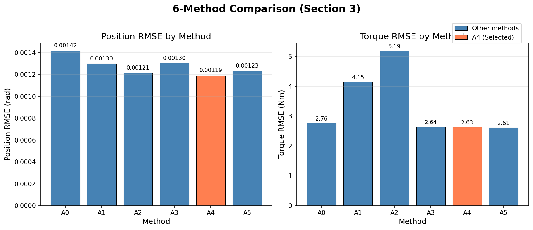
Position RMSE (left) and Torque RMSE (right) comparison. A4 (LPF) is the optimal balance point
Position RMSE Ranking:
| Rank | Method | RMSE (rad) | Improvement |
|---|---|---|---|
| 1 | A4 (LPF) | 0.001190 | +16.0% |
| 2 | A2 (ABG) | 0.001212 | +14.4% |
| 3 | A5 (Jerk) | 0.001231 | +13.1% |
| 4 | A1 (NumDiff) | 0.001297 | +8.4% |
| 5 | A3 (Planner) | 0.001302 | +8.1% |
| 6 | A0 (None) | 0.001416 | Baseline |
Torque RMSE:
| Method | Torque RMSE | Evaluation |
|---|---|---|
| A5 (Jerk) | 2.61 Nm | Stable |
| A4 (LPF) | 2.63 Nm | Stable |
| A3 (Planner) | 2.64 Nm | Stable |
| A0 (None) | 2.76 Nm | Baseline |
| A1 (NumDiff) | 4.15 Nm | +50% (Warning) |
| A2 (ABG) | 5.19 Nm | +88% (Eliminated) |
Reason A2 (ABG) was eliminated: Good position but torque variation too high.
Experiment 2: LPF Parameter Tuning
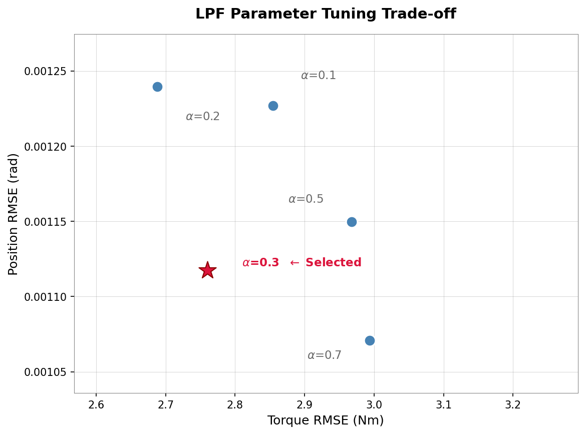
Position RMSE vs Torque RMSE tradeoff by alpha value. alpha=0.3 selected
| Alpha | Cutoff Frequency | Position RMSE | vs alpha=0.2 | Torque RMSE |
|---|---|---|---|---|
| 0.1 | ~16 Hz | 0.001227 rad | +1.0% | 2.85 Nm |
| 0.2 | ~32 Hz | 0.001240 rad | Baseline | 2.69 Nm |
| 0.3 | ~48 Hz | 0.001118 rad | -9.8% | 2.76 Nm |
| 0.5 | ~80 Hz | 0.001150 rad | -7.3% | 2.97 Nm |
| 0.7 | ~112 Hz | 0.001071 rad | -13.6% | 2.99 Nm |
Reasons for Selecting alpha=0.3:
- Position improvement: 9.8% improvement compared to alpha=0.2
- Torque stability: 2.76 Nm, nearly identical to baseline (2.77 Nm)
- Safety margin: alpha=0.7 has 11.2% torque increase
Experiment 3: Final Benchmark
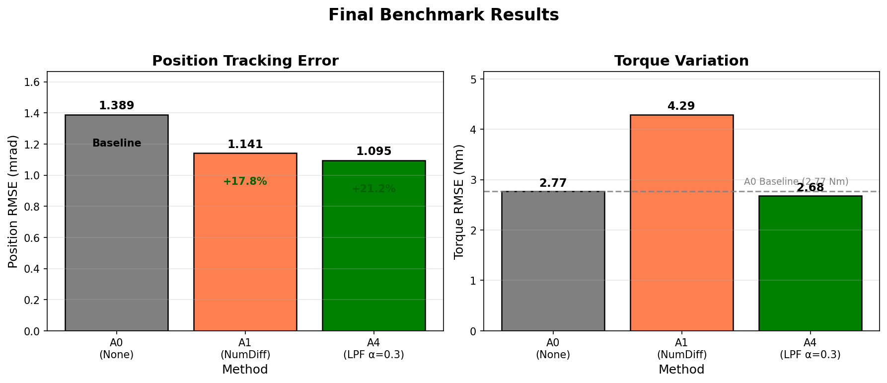
Final comparison of A0 (baseline), A1 (numerical differentiation), A4 (LPF)
Position Tracking Performance:
| Method | Position RMSE | Std Dev | Improvement |
|---|---|---|---|
| A4 (LPF) | 0.001095 rad | 0.000087 | +21.2% |
| A1 (NumDiff) | 0.001141 rad | 0.000064 | +17.8% |
| A0 (None) | 0.001389 rad | 0.000071 | Baseline |
Torque Stability:
| Method | Torque RMSE | Std Dev | Evaluation |
|---|---|---|---|
| A4 (LPF) | 2.68 Nm | 0.37 | Stable (-3%) |
| A0 (None) | 2.77 Nm | 0.52 | Baseline |
| A1 (NumDiff) | 4.29 Nm | 1.04 | Unstable (+55%) |
Why Planner Acceleration Alone (A3) Is Insufficient
Using planner acceleration directly without filtering achieves only 8.1% improvement (half of A4).
Cause: Jerk discontinuity at waypoint boundaries generates high-frequency components that burden the controller.
Why LPF (A4) Is Better Than Jerk Limiting (A5)
| Aspect | LPF | Jerk Limiting |
|---|---|---|
| Response characteristic | Exponential decay | Linear ramp |
| Convergence speed | Fast initial response, gradual convergence | Constant rate approach, slow convergence |
| Example: delta_acc=20 rad/s^2, MAX_JERK=50 rad/s^3 | Fast | 400ms required |
Warm-up Effect
We discovered a warm-up effect during experiments:
| Condition | Before Warm-up | After Warm-up | Difference |
|---|---|---|---|
| A3 (Planner) | 0.001532 rad | 0.001302 rad | 15% improvement |
Implication: Performance can degrade by 15% on cold start. This should be considered in actual robot operation.
Experimental Conditions
| Parameter | Value | Reason |
|---|---|---|
| Test joint | J1 (shoulder) | Maximum friction (Fc=35Nm) maximizes FF effect |
| Velocity scale | 0.3, 0.4, 0.5 | Differences clearer at high speeds |
| Acceleration scale | 0.5 | High acceleration condition |
| Repetitions | 4 per speed | Direction balance (2 forward + 2 reverse) |
| Trajectory | +/-30 deg toggle | Standard test motion |
Key Takeaways
-
Limitations of existing numerical differentiation (A1): Phase delay and noise amplification from discrete differentiation increases torque variation by 55%.
-
ROS2 JTC already computes acceleration. Planner acceleration can be directly utilized without separate numerical differentiation.
-
Jerk discontinuity problem: Using planner acceleration without filtering degrades performance due to high-frequency components at waypoint boundaries.
-
Optimal method: LPF (alpha=0.3)
- Position RMSE: 21.2% improvement
- Torque RMSE: 3% reduction
- Simultaneously improves position accuracy and torque stability
-
Warm-up effect: 15% performance degradation may occur on cold start.
A simple first-order Low-Pass Filter was the optimal solution that improves both position accuracy and torque stability simultaneously.